www.lighttoolsupply.com

Thursday, November 11, 2010

Stanford University turns to the precision of Fagor Automation encoders

Stanford University turns to the precision of Fagor Automation encoders
Posted by World in General, Product

The Stanford Linear Accelerator Center is a multi-research center for astrophysics, photovoltaic science, molecule accelerator and research on physical particles. Center running under the Energy department of the US government and Headquarters of the current 3km-diameter accelerator ring, one of the largest in the world.
The SSRL is inside this laboratory (Stanford Synchrotron Radiation Ligthsource), is located inside this facility, that currently uses 20 absolute linear encoders from Fagor Automation.
This lab is supplier of synchrotron radiation. I.e. X rays produced by the electrons that circulate through a ring at near-light speed. This beam of X-rays is used to investigate the behavior of the molecules and atoms of materials with extraordinary properties.
Very important activity for our society because nowadays the basis of new technologies today is the creation of new materials that may have considerable impact in areas like environment, future technologies, health or education.
Repeatability and flexibility granted by programmable resolution are of utmost importance in X-Ray crystallography used in this center.
X-ray crystallography is a method of determining the arrangement of atoms within a crystal, in which a beam of X-rays strikes a crystal and diffracts into many specific directions. From the angles and intensities of these diffracted beams, a crystallographer can produce a three-dimensional picture of the density of electrons within the crystal. From this electron density, the mean positions of the atoms in the crystal can be determined, as well as their chemical bonds, their disorder, etc.
Using X-ray crystallography, the scientists of this center can determine the molecular structure of biological proteins and that”s how Dr. Roger David Konberg was awarded the Nobel Prize in Chemistry in 2006 for his studies of the process by which genetic information from DNA is copied to RNA.
This lab uses 5 operating systems that include these Fagor Automation high resolution measuring systems and they foresee building more of them.
These operating systems have 10 axes with various functions. The axes control what is called the collimator, they must move horizontally to provide the highest crystal diffraction quality. The speed and accuracy of this movement is extremely important for SLAC researchers. In neutron, X-ray and gamma ray optics, a collimator is a device that filters a stream of rays so that only those traveling parallel to a specified direction are allowed through.
Collimators are used in neutron, X-ray, and gamma-ray optics because it is not yet possible to focus radiation with such short wavelengths into an image through the use of lenses as is routine with electromagnetic radiation at optical or near-optical wavelengths Collimators are also used with radiation detectors in nuclear power stations for monitoring sources of radioactivity.
Another 2 additional axes control what is called the Kappa Goniostat, micro-diffractometer where the crystal is mounted to detect the X-rays.
The ganiostat are designed to allow an accurate positioning of the sample centered in a wide range of positions.
Once again, the repeatability and flexibility offered by Fagor Automation scales is extremely important for the research carried out by this pioneering research center that is visited by more than 3000 scientists from all over the world.

Order Fagor Digital Readouts at http://www.lighttoolsupply.com

Thursday, November 4, 2010

Gaging Tips

Get the Most From Your Form Measuring System
George Schuetz, Mahr Federal Inc.
http://www.mahrfederal.com/

With the implementation of touch screen operation, canned measurement routines and automatic ranging, form measuring machines have become nearly foolproof and have successfully migrated from the lab to the shop floor. Still, the form machine is only as good as its setup, and without due attention to the basics, there are many pitfalls that can make even the most basic measurement useless. In this column we will highlight some of the most common problems to watch out for.
"Stage it to gage it:"
As with any dimensional check, unless a part is staged correctly, unwanted errors are apt to show up in the measurement results. Often a three-jaw chuck is used to stage a work piece. But when used on a thin-walled part this may introduce a three-lobed condition in the measurement. Likewise, special clamping may be needed to help stabilize a tall narrow part.
Using the wrong stylus tip:
Often the operator of a form measuring system will only use the probe initially supplied with the machine, regardless of the size of the part being measured. But the stylus tip really acts as a mechanical filter and needs to be selected according to part diameter and the maximum number of undulations per revolution relative to the application. The manufacturer of the form machine probably has a whole host of measuring probes available for the transducer. Besides different ball sizes and contact shapes, other materials may be required. Sometimes conflicts between the part and the tip may cause probe chattering or even "picking up" material on the probe and changing its characteristics over time.
Choosing the wrong type of signal processing filter:
Originally, the filters in form measuring systems were analog and used resistors and capacitors. These were referred to as 2RC filters. When computers started taking over the form tasks, digital filters were created to simulate these 2RC filters. The newest systems utilize digital Gaussian filters. These are more accurate than the 2RC filters and tend to introduce less distortion. Because of these characteristics they are becoming the filter of choice in the newer standards. Be aware that older systems will not correlate with new form systems which may make them obsolete to the standards.
Confusion over the way the results "look:"
The results of a form measurement rarely look "round" on the computer screen or printout. Often, the trace has sharp high and low points which can fool the user into thinking the part has terrible form errors.
Computer-based form systems normalize the deviation around a fixed circle. The operator then chooses the best magnification to balance the form error to the specific surface deviations. While the computer trace does not accurately represent the part's actual profile, the relationship between the highs and lows remains consistent with the system's magnification and represents accurate angular relationships around the circumference of the trace.


Measuring the wrong parameter:
Often there is confusion over geometry parameters. For example, in the case of a simple indicator gage, the term "run out" and "out-of-roundness" are used interchangeably. However, they are not the same when measuring form, and need to be measured differently. Similarly, when gaging perpendicularity, parallelism and other parameters involving relationships between two surfaces, the user must understand which surface needs to be measured first.
For example, the statement often seen on a print, "B is parallel to A" is not the same as "A is parallel to B." By definition, the second surface in the statement is considered the reference or datum surface. All of these parameters and more are defined in the ANSI Y14.5M Standard.
Inattention to centering and leveling:
As part of staging, proper centering and leveling are critical elements for correct form measurement. A round part that is not level will produce an oval trace, while an off-center part will produce a trace that almost resembles a heart. If the form gage has a fixture to quickly align the part, it is wise to make sure that the part is in the fixture properly and is centered and aligned. Even if the form machine has centering and tilt correction as part of its software package, the closer you get to true center and level, the better your results will be.
These are only a few of the most common form measurement problems. Next month, we'll take a look at a few more things that will help improve your form measurement process.

Order Mahr/Federal Tools at http://www.lighttoolsupply.com

Friday, October 29, 2010

Meyer Gage Announces Improvements to Better Serve You

Meyer Gage Announces Improvements to Better Serve You

 
New Calibration Laboratory
 
Lab
South Windsor, CT - October 29, 2010  Meyer Gage Company Inc has just completed a new calibration and final inspection laboratory.  The new laboratory will allow for more precise temperature and humidity control resulting in lower measurement uncertainty.  The laboratory is 20' x 44' and includes a custom designed HVAC system with microprocessor for precise automatic environmental control.
 
Meyer Gage acquires the following equipment as part of our continuous improvement process

Pratt & Whitney LabMaster Universal®


With instrument uncertainty to 2 millionths of an inch (50 nanometers), the Labmaster Universal (LM U306270) is suitable for virtually all Internal (ID) and external (OD) measuring applications. This laser-based universal length measuring system (ULM) has been developed by Pratt & Whitney for gage calibration laboratories that need to precisely measure length, outside diameter, inside diameter, pitch diameter, lead, major/minor diameter, taper, linear displacement, and thickness.
High accuracy is maintained by its laser interferometer, zero Abbe offset design, and large measuring table with center position, height, pitch, and yaw controls. The computer-controlled precision air bearing slide and gaging fingers remove operator-influenced errors commonly observed with traditional gaging methods by maintaining constant force.

The ULM is capable of measuring gage blocks, end standards, plain rings, threaded rings & plugs, API gages, pin & plug gages, tapered plugs, cylindrical setting gauges, micrometers, indicators, LVDTs, calipers, and snap gauges with instrument uncertainty to 2 millionths of an inch (0.05 micron). It is suitable for virtually all ID and OD applications through its wide 0.020-inch (0.5 mm) to 14-inches (356 mm) measuring range. The ULM includes Pratt & Whitney's GageCal software that automatically enters tolerances for rings, plugs, pins, balls, threads (calculates pitch/major diameter) and flags out of tolerance conditions.
.

Meyer GageOrder Meyer 

Tuesday, October 26, 2010

#Milwaukee #Tool Sponsorship of #Cain #Velasquez is a Winner


Milwaukee® Steps into the Ring with Cain Velasquez

    “Heavy Duty” meets “Heavyweight” as Milwaukee Electric Tool announces a new exclusive partnership with Mixed Martial Artist, Cain Velasquez. With a shared commitment and respect for the trades, Milwaukee® and Velasquez have united to represent hard work, determination and a passion to win; core values of both Milwaukee users and MMA fans alike.
    “For over 85 years, Milwaukee has led the power tool industry with innovative solutions that help the professionals stay at the top of their game on and off the job-site” says Steve Richman, President, Milwaukee Electric Tool Corporation. “Teaming up with Cain Velasquez is a perfect match for Milwaukee, both are obsessed with being the best at what we do, and share a long history of uncompromising passion for winning”.
    Currently competing in the UFC® Heavyweight Division, Cain Velasquez is a two-time All-American collegiate wrestler from Arizona State, a Junior College National Champ at Iowa Central Community College and a two-time 5A state champion in Arizona, compiling a record of 110-10 in high school competition.  A determined presence in the ring, Cain has never lost a round in mixed martial arts competition.
    Cain Velasquez will be facing current Heavyweight Champion Brock Lesnar for the UFC® Heavyweight Championship in UFC® 121 on October 23, 2010 in Anaheim, California.  The Milwaukee Velasquez partnership will extend throughout 2011 with multiple distributor appearances across the western and southwestern regions of the US.


About Milwaukee Electric Tool Corporation
Milwaukee Electric Tool Corporation, a Brookfield, Wisconsin-based subsidiary of Techtronic Industries Co. Ltd. (TTI) (HKEx stock code: 669, ADR symbol: TTNDY) is an industry leading manufacturer and marketer of professional, heavy duty power tools and accessories.  Products include the legendary SAWZALL® reciprocating saws, M12™, M18™ & M28™ LITHIUM-ION cordless tools, HOLE-HAWG® drills, portable band saws, circular saws, driver drills, hammer drills, rotary hammers, grinders, sanders and a line of Test & Measurement tools.  Accessories include SAWZALL® blades, SWITCHBLADE® self-feed bits, BIG HAWG®


http://www.lighttoolsupply.com


Thursday, October 21, 2010

Mahr Federal Gaging Tips


New Parts, Tighter Tolerances:  You Can Gage Them, But…
George Schuetz, Mahr Federal Inc.
http://www.mahrfederal.com/

If you are planning on manufacturing to tolerances of .0001" or less, and have not done so before, your introduction to high order gaging may be an eye opener. Gaging at this level is a very different animal, especially when considering how to measure the new parts you will be producing.
When gaging parts with the usual tolerances (0.0005" or broader), the quality of the gage is usually the main consideration. However, when you become interested in tolerances of say 30 µinches, there is much more than the gage to consider. You must place just as much importance on creating a special environment in which it will operate.
But even before thinking about the gage or the environment, a decision must be made about what should be measured: the size of the part, or the relationship of the part to another part. The answer to this can make a big difference in the cost and difficulty of getting the desired results. At these tighter tolerances, it is much less difficult and often more effective to check part relationships—clearance for example—rather than part dimensions.
If the decision is to check size, new methods of production measurement will be needed. Using the old 10X rule of thumb, for a 30 µinch tolerance, the repeatability of the gage needs to be in the 3 µinch range; and to be sure both the gage and the master have such accuracy we would need a master that is accurate to 0.3 µinches. Since no one would guarantee a master or even a gage block to have this accuracy, the best you can do is use the best standard available, which is apt to be a set of carefully cleaned and properly wrung Lab Master or Grade 0.5 (AAA) gage blocks with a ±1 µinch tolerance.
Now you need to focus on the environment. We all know the influences, but unfortunately, they are too often underrated. Particular attention must be paid to temperature and cleanliness. Within limits, temperature itself is not as important as its consistency and the degree to which it is shared by the gage, the master, the part, and the surrounding atmosphere. For example, if you are checking the diameter of a 0.5 inch bore, a temperature difference of only one degree between the part and the master is likely to introduce an error of about 3 µinches. In addition, if the room temperature shifts a few degrees, or the operator's body heat is allowed to reach the gage, it is easy to accumulate a few more millionths of error.
Here are a few tips that can help control the needed environment.
Parts, master and even the gage should be part of one large heat sink, if possible, so they can all be brought to the same temperature and held there. The larger the mass of the gage and heat sink, the less likely it will change during sudden air temperature changes. Even with the heat sink in place, it may take hours for the parts to normalize. Gaging must take place in a constant temperature room and the parts must be measured without touching them: the use of insulated gloves or tweezers is a must.
Assuming these recommendations are followed, it will still be necessary to check the gage frequently and compensate accordingly. No one can predict how the opening of a door and the resulting draft that occurs will affect the measurement. It may even be necessary to try to isolate the operator from the gaging process by placing a thermal shield between the operator and the gage—all in an effort to save microinch errors.
The problem of dirt can be just as troublesome. Dirt particles or film, which is virtually invisible, can easily cause serious repetition errors. It will likely be necessary to chemically clean the entire gaging area periodically (there is no way to predict how often—only experience will tell). Part cleaning will vary somewhat depending on shape, material and size, but methods and cleaning fluids will have to be studied since residue can't be ignored at these tolerances. And don't forget that residue may also build up on gage contacts after repeated measurements.
Taking these steps into account—with thorough planning, careful personnel selection and training, along with significant investment in proper equipment—will help achieve measuring to these tight tolerances. Anything less, i.e., cutting corners, can ruin the economics of the job and cost more in the long run.
This ID/OD gage has all the elements necessary for millionth measurements—when used in a temperature controlled room—including a large granite base, set up with gage blocks, and millionth readout.

Thursday, October 7, 2010

http://www.lighttoolsupply.com

To purchase Mahr Products 
Contact


For full line of Mahr products check 

Micrometers -
Measuring under the influence:

The basic micrometer is one of the most popular and versatile precision hand-held measuring tools on the shop floor.  While the most common type is the outside diameter style, the principle can be used for inside diameters, depths and grooves.  With so many options for holding the spindle and alternate contact points available, it's a tool to satisfy an endless number of measurement applications.
The biggest problem with micrometers is that measurements are subject to variations from one operator to another.  There are two types of influences that contribute to this variation: "feel" or inconsistent gaging force, and subjective factors.
The micrometer is a contact instrument.  Sufficient torque must be applied to the micrometer to make good positive contact between the part and the instrument.  The only torque calibration in the human hand is the operator's "feel."  What feels like solid contact to one operator may not feel correct to another, so the readings will be different.  In order to eliminate the "feel" part of the measurement, the designers of micrometers incorporated a ratchet or friction thimble mechanism.  This is an attempt to assure more consistent contact pressure and eliminate the human influence.
A psychologist might say that the other types of measuring influences, the subjective ones, are all in the operators' heads.  Tell an inspector that the best machinist in the plant made this part and influence enters the picture.  Or suppose your boss walks over and asks you to measure a part and he adds, "I just made it myself."  In these cases, measurements will tend to be better than the part deserves.
There are also more subtle types of influences.  For example, if you know what size the parts ought to be before you measure them, readings will tend to be closer to that ideal than if the target dimension were unknown.
  
Don't take my word on this, conduct your own experiment.
Step 1: Take a number of workpieces and have several people measure them using micrometers without a clutch or ratchet or friction type thimble.  Don't reveal the actual dimension of the workpiece or what anyone else got for readings.  These are uninfluenced measurements.
Step 2: Give the same operators a known test piece to practice on to get a feel for obtaining a repeatable reading.  Then ask them to measure an unknown part.  Next give another group a sample known part to practice on to get a feel for obtaining a repeatable reading; then have them measure parts where the size is known.  These are influenced measurements and I'm willing to bet good money that there will be significantly less variation in these results.  It's just human nature.
Step 3: Replace the micrometer with one with a ratchet or friction thimble.  The measurements are likely to improve even more.
Now that you have a better understanding of measuring under the influence you can do something about it.  The simplest thing to do is use a hand tool that has ratchet or friction drives to achieve more consistent gaging pressure.  Or, in the case of the micrometer, the best way to obtain the most consistent reading is with an indicating micrometer.  This type of micrometer combines the flexibility of range with the high resolution and consistent gaging force of a dial indicator.
The lower anvil of an indicating micrometer is actually the sensitive contact of a built-in indicator which provides readings (it's typically in 1um/50u" gradations) clearly and quickly with no vernier to read.  Like the standard micrometer, you can adjust the spindle to the size needed and obtain a consistent gaging force when the master is set to zero on the dial indicator.  Once established, the spindle is locked into position.  Now the measuring tool begins to act like a gage by making measurements in a comparative mode.  A retraction lever is also incorporated in the gage, making it easy to position the part for measurement quickly and to reduce wear on the contacts.
An indicating micrometer is a perfect gage for medium run, high tolerance parts.  With this one gage an experienced operator can quickly set up the measurement process.  Once the gage is locked in place, the indicating micrometer applies identical gaging pressure for each measurement, regardless of who is using it.  The novice quickly obtains the same uniform high accuracy results as the experienced inspector regardless of differences in feel or what is known or not known about the part.
 
Micromar Micrometers-
Everything rotates around precision
Micrometers together with calipers are the most frequently used hand measurring instruments. Our mechanical micrometers are extremely reliable and easy to read while digital micrometers40A.jpg combine the precsion from Mahr with the most modern electronics. Micromar 40A series of mechanical micrometers provides a number of standard configurations that ensure precise and reliable results are obtained even in the most difficult shop conditions .

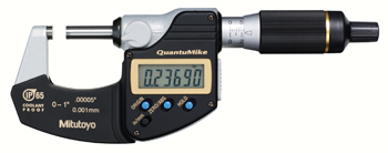
Free #QuantuMike with select Mill Kits offer


                                              http://www.mitutoyo.com
            Free QuantuMike with select Digital Readout Kits below


Effective immediately and valid through December 17, 2010, Mitutoyo America Corporation (MAC) is offering
a free 293-185 QuantuMike ($202.00 value) to domestic US customers with the purchase of any of the following
Absolute DRO packages for milling machines;

·         174-173PM1K             12” X 30” package for Bridgeport Mills
·         173-173PM2K             12” X 36” package for Bridgeport Mills
·         174-173PM5K             16” X 36” package for Universal Type Mills
·         174-173PM10K           12” X 36” package for Universal Type Mills

Upon receipt of the product, the customer can visit the Mitutoyo America website at www.mitutoyo.com,
navigate to the Product Registration link and fill out the required information (Model Number and Serial Number of the KA-12 Digital Readout required).

This offer is valid for end user customers only.  Requests to ship the free QuantuMike to MAC distributor addresses will not be processed.
For additional information, please contact us at Click Here To View Complete Offer

Purchase the Digital Readouts that qualify for offer please contact