Temperature Compensation -
It's time is here
Temperature variation is one of the most significant sources of gaging error. As manufacturing tolerances get tighter and the margin for gaging error gets smaller, it becomes an issue that must be addressed. Most materials expand as they heat up. For every inch of steel, a 1°F increase causes expansion of approximately 6µ". For brass and copper, the figure is 9µ", and for aluminum, 13µ". If the objective of the inspection process is to determine a part's true size, its temperature must be known. Based on the ISO's very first standard (ISO 1 issued in 1931) that temperature is automatically assumed to be 68°F (20°C).
But few inspection processes monitor, much less attempt to control, workpiece temperature. Many quality managers assume that any thermally induced variation in the part will be matched by like variation in the gage and the master: everything will expand and contract at the same rate, and everything will work out just fine.
This is far from true. Gage, master, and part—the three hardware "components" of a gaging system—may be of different materials, so the effects of thermal expansion will differ even if they're all at the
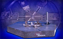 same temperature. And the components won't necessarily be the same temperature. Parts that have recently come off a dry machining process may be several degrees warmer, and may remain so for hours. Parts machined under coolant may be cooler. The gage or the master might be sitting on a bench in direct sunlight, or under a heating or cooling vent. Temperature stratification within a room may create temperature differences between components placed near the floor, and components placed on a high shelf. The relative masses of the components may make a difference. For example, an engine block may take longer to reach equilibrium with ambient temperature than a bore gage. And in some instances, thermal variation may work in opposite directions for the gage and the workpiece, compounding rather than canceling the error. For example, high temperatures will cause bore gage contacts to grow longer, which will naturally result in ID measurements that are smaller than actual. On the other hand, the ID of a thin-walled part, like a bearing shell, will grow larger with higher temperatures. To read the remainder of this article "click here"
 Millimar Inductive Probes
The requirements for electrical length measuring instruments are almost as broad as their scope of application. Reliability, precision and simple operation are the major demands. Millimar bench amplifiers and column measuring instruments fulfill all these demands and requirements. Millimar probes are the most influential components of a measurement process. Their characteristics determine the quality of the entire measurement. Depending upon the type of application Mahr Federal has the right probe for your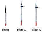 requirements. For example, Millimar Inductive Probes are robust, versatile and provide high value for their cost while Millimar Incremental Probes are ideal for long range measurement applications becasue they provide high linearity over their entire measuring range.
 - Available for most common amplifier systems (Mahr, Mahr-Federal, Tesa, Marposs)
- Wide product spectrum; measuring ranges from 1 to 10 mm plus models with a compressed air (pneumatic) lifter or with vacuum retraction
- With rotary stroke bearings
- High linearity over the total measuring range
- Excellent electromagnetic shielding (EMC)
- Most probes can be easily converted from axial to radial by mounting a slip on cap, included in the scope of supply.
No comments:
Post a Comment